How to Reduce the Part Deformation During CNC Machining?

It is really a headache when you got a CNC machining part that was deformed, not flat so you could not assemble it, as a result, it stops your project.

The deformation of aluminum alloy processing is a difficult problem faced by many CNC machining plants. So how can the aluminum alloy not be deformed? First of all, we must understand the reasons for the deformation of aluminum alloy in the CNC machining process.

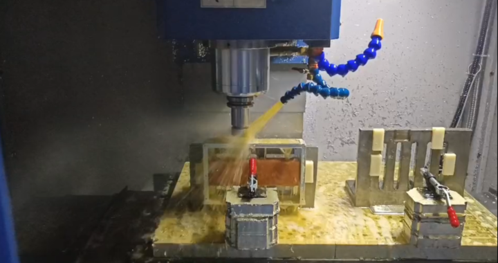
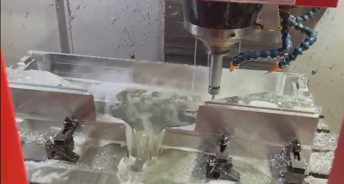
Aluminum alloy processing is completed by cutting the material with a tool. The cutting process is the extrusion process. The extrusion process will generate a lot of heat, the material will expand, and the grain of the material will change. After cooling, it will shrink and the grain structure will change, resulting in the metal Residual stress will be generated inside, this stress will be deformed if not eliminated, and the size will also change.

The solution to solve this problem is to divide the aluminum alloy machining process into roughing and finishing. After the roughing is completed, the parts are heat-treated to fully release the cutting stress and residual stress of the parts, and then finish machining; the advantages are:

-1> The influence of residual stress on machining deformation can be reduced. After rough machining is completed, it is recommended to use heat treatment to remove the stress caused by rough machining of the part, which can reduce the influence of stress on finishing.

-2> Improve machining accuracy and surface quality. After the roughing and finishing are separated, the finishing is only a small allowance, and the processing stress and deformation are small, which can greatly improve the quality of the parts.

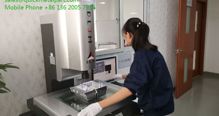
Quick Metal Part could provide professional workmanship to avoid deformation parts and please send your CAD file if you have flatness requirement on the part surfaces.


Consider These Factors Before Lunch Production Your Designed CNC Parts

We are very happy to feedback to the Process FMEA when we got your CNC machining part RFQs and these factors that we always discuss with our clients to quickly improve your designing parts in the production:

  • Your CNC machining part needs what kind of material and finish treatment – it meant what the part-work environment is: Withstand high temperature, using it at the outside door,…etc;
  • Choice the production process to realize your CNC machining part – Based on the part structure and material, we will advise the best solutions for you;
  • Reviewing Your CAD file so we can advise if any updates are needed for the part profile, structure, and details if could be machined or not.


Sheet Metal Part Fabrication Process

The production process for Sheet Metal Part Fabrication at Quick Metal Part:

  1. Working out the Engineering production part drawings per customer CAD files;
  2. Laser – Cutting Sheet Metal Raw Material;
  3. Sheet Metal Forming;
  4. Sheet Metal Part Bending;
  5. Sheet Metal Part Welding;
  6. Install the PEM parts / Hardware Insertion;
  7. Sheet Metal Part Assembly;
  8. Sheet Metal Part Powder Coating, Silk Screen, Anodizing, E-Coating etc.
  9. Sheet Metal Part Out-Going Inspection;
  10. Shipping.

How to Save the CNC Machining Part Cost

We are often being asked how to reduce the CNC machining part cost?

Well. This is really a common question from many customers and here Quick Metal Part would like to list the following reasons:

  1. CNC Machining Time: This is the essential factor for why your CNC machining part cost is so high – The longer machining time, the higher CNC machining cost;
  2. CNC Part Tolerance: Tolerance is the most important satisfaction for most customers that we need to take care of it – The cost will be higher for small tolerances;
  3. Select the economic CNC part Material and Finish Treatment – Please see the material list from our CNC machining Menu;
  4. Increase the CNC Part wall thickness when you designing the CNC machining parts;
  5. For the holes and threads of your CNC machining parts – please try to tap the standard hole size and threads;
  6. Change the inner corner to Radius to save the cost of cleaning the corner of the parts.

What is Rapid prototyping?

Rapid prototyping is a group of techniques used to quickly fabricate a physical part or assembly using three-dimensional computer-aided design (CAD) data.

Construction of the part or assembly is usually done using 3D printing or “additive layer manufacturing” technology.

The first methods for rapid prototyping became available in the mid-1987 and were used to produce models and prototype parts. Today, they are used for a wide range of applications and are used to manufacture production-quality parts in relatively small numbers if desired without the typical unfavorable short-run economics. This economy has encouraged online service bureaus. Historical surveys of RP technology start with discussions of simulacra production techniques used by 19th-century sculptors. Some modern sculptors use progeny technology to produce exhibitions and various objects. The ability to reproduce designs from a dataset has given rise to issues of rights, as it is now possible to interpolate volumetric data from one-dimensional images.

As with CNC subtractive methods, the computer-aided-design – computer-aided manufacturing CAD-CAM workflow in the traditional rapid prototyping process starts with the creation of geometric data, either as a 3D solid using a CAD workstation, or 2D slices using a scanning device. For rapid prototyping this data must represent a valid geometric model; namely, one whose boundary surfaces enclose a finite volume, contain no holes exposing the interior and do not fold back on themselves. In other words, the object must have an “inside”. The model is valid if for each point in 3D space the computer can determine uniquely whether that point lies inside, on, or outside the boundary surface of the model. CAD post-processors will approximate the application vendors’ internal CAD geometric forms (e.g., B-splines) with a simplified mathematical form, which in turn is expressed in a specified data format which is a common feature in additive manufacturing: STL file format, a de facto standard for transferring solid geometric models to SFF machines.

To obtain the necessary motion control trajectories to drive the actual SFF, rapid prototyping, 3D printing, or additive manufacturing mechanism, the prepared geometric model is typically sliced into layers, and the slices are scanned into lines (producing a “2D drawing” used to generate trajectory as in CNC’s toolpath), mimicking in reverse the layer-to-layer physical building process.

Sheet metal forming challenges

Sheet metal forming, which is often referred to as stamping, is a process in which a piece of sheet metal, referred to as the blank, is formed by stretching between a punch and a die.

The most painful and most frequent defects are wrinkles, thinning, spring back, and splits or cracks. Few methods are being used around the industry to cope with the main defects, based on the experience of the technicians. However, the correct process is the most vital, since it involves the correct geometry followed by a number of steps to reach the final geometry. Which demands a specific experience or a higher number of iterations.

Deformation of the blank is typically limited by buckling, wrinkling, tearing, and other negative characteristics which makes it impossible to meet quality requirements or makes it necessary to run at a slower than desirable rate.

Quickmetalpart would use the easy-quick tooling to help you get the quick stamping part for 1,000pcs without any defect if you do not want to spend the huge cost on stamping toolings.

What is CNC machining?

CNC Machining is a rapid process in which a material is cut to a desired final shape and size by a controlled material removal process.

The processes that have this common theme are collectively called subtractive manufacturing, which utilizes machine tools, in contrast to additive manufacturing), which uses controlled addition of material.

The principle of CNC machining of aluminum alloy is to use the automatic control system to install a digital program process to control the automatic start-stop, reversing, and speed change of the machine tool. Machining can select CNC tools, and change the tool holding force and walking trajectory according to the CNC tools to complete various actions required in processing. CNC machining of aluminum alloy products, 90% of the products can be completed independently by CNC machine tools, and do not need to be processed by other machines.

Machining is a part of the manufacture of many metal products, but it can also be used on other materials such as wood, plastic, ceramic, and composite material. A person who specializes in machining is called a machinist. A room, building, or company where machining is done is called a machine shop. Much of modern-day machining is carried out by computer numerical control (CNC), in which computers are used to control the movement and operation of the mills, lathes, and other cutting machines. This increases efficiency, as the CNC machine runs unmanned therefore reducing labor costs for machine shops.